Manual work station
for processing fasteners
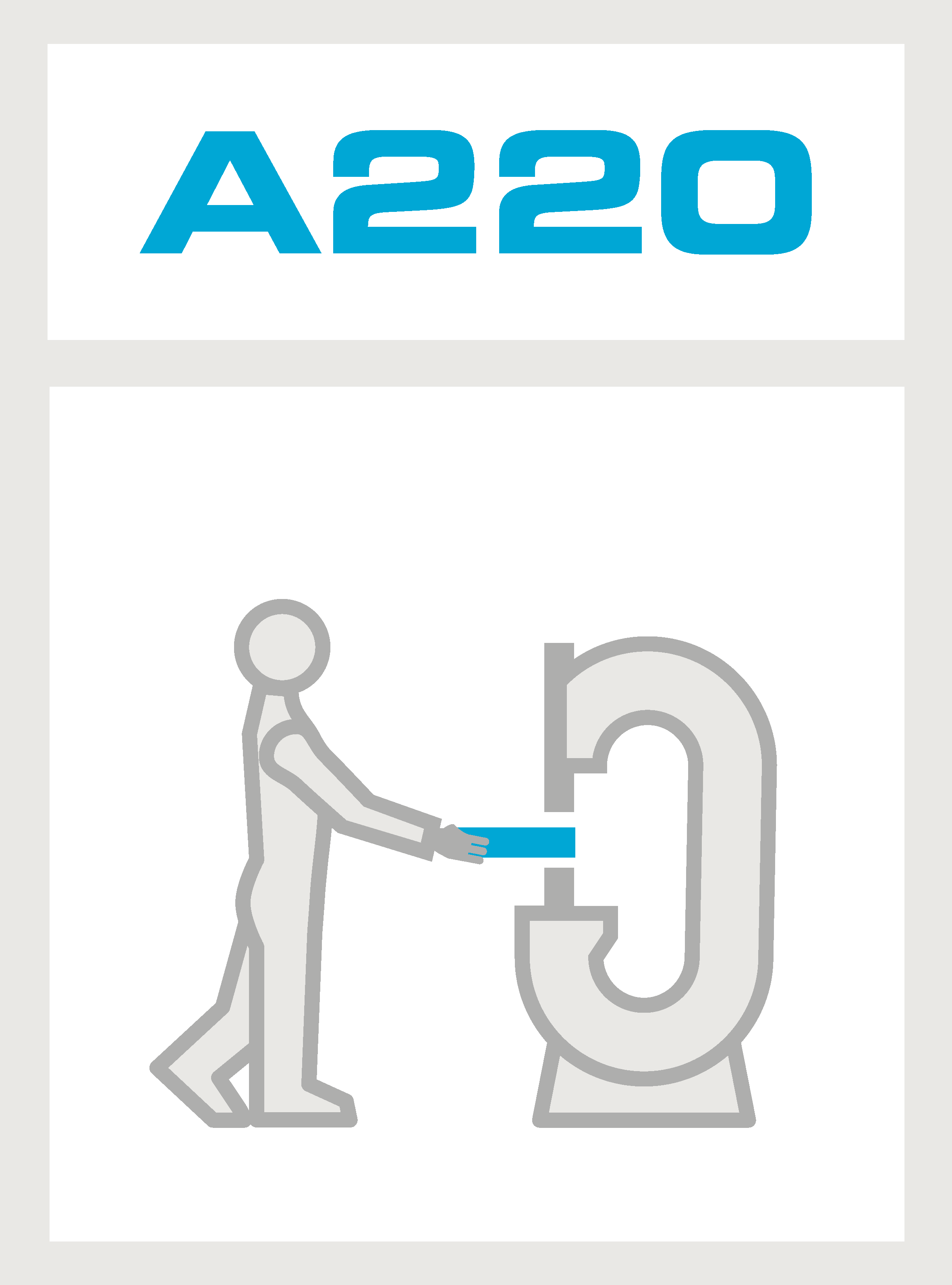
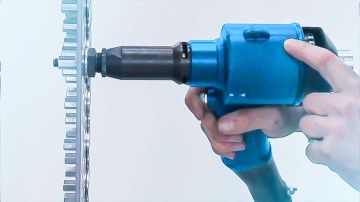
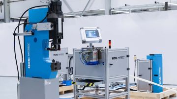
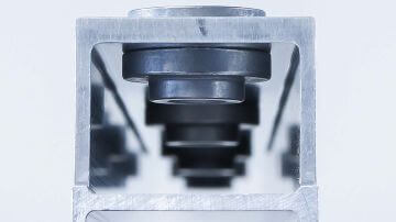
The A220-CP (Clinch Parts) assembly system is a stationary manual work station for processing clinching fasteners.
The design of the assembly system is similar to A240-CP robotic work station with the difference that the processed sheet metal component is placed by the operator and is not held by the robot. The feeding of the clinching fasteners can be done either by a feeding system or manually.
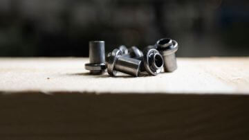
Fasteners - Clinch nut, rivet nut, self-piercing nut, clinch stud, self-piercing stud / rivet stud
Thread size - M5, M6, M8, M10, M12
Working direction - From top to bottom
Advantages of the system
- Process-reliable processing of clinching fasteners
- Parallel drive (patented) for efficient tool movements and low wear
- Low compressed air consumption and active tool protection
- Active tolerance compensation (patented)
- Feeding system and controller module outside the danger zone
- Integrated displacement measurement system with active pre-stroke before the setting stroke
- Process monitoring with force-displacement evaluation
Designs
Manual work stations for various fasteners
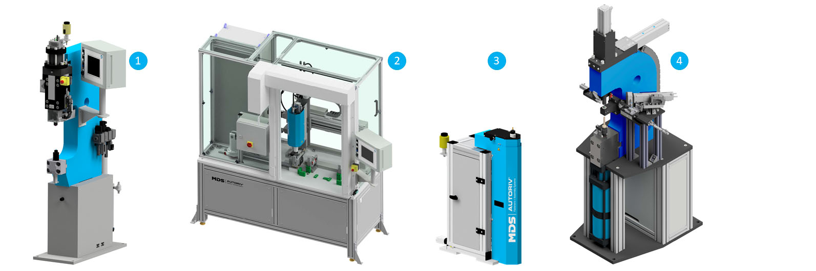
The manual work stations are available in different versions. Thus, other types of fasteners can be processed:
Manual work station A220-BI (Blind Inserts) for blind rivet nuts and blind rivet studs
Variant with working direction from top to bottom (2)
The setting process is similar to "A230-BI mobile robotic tool". The processed sheet metal component is inserted by the operator and the setting unit is moved to the component.
Variant with working direction from bottom to top (3)
The setting process is similar to A230-BI, except that the processed sheet metal component is placed on the setting unit by the operator, the setting unit is not moved to the component.
Manual work station A220-NMS for combination of a nut and spacer (4)
The nut-spacer-combination is a high-strength structural connection for joining positions accessible from one side, e.g. in closed profiles.
This manual work station is used to set clinch nuts / rivet nuts in combination with additional spacers / washers in a single step. The spacer is inserted into the die by a transfer mechanism with gripper. The operator places the component on the inserted washer. The plunger feeds the nut and performs a setting stroke that connects the clinch nut and spacer to the component.
Function
In the start position, all machine components are in the home position. The clinching fastener is supplied by the feeding system or inserted manually into the holder. Next, the component is positioned correctly with both hands and, if necessary, held in place if the operation is activated via the foot switch.
In automatic mode, the setting process is started and performed automatically with the two-hand operation or foot switch. The plunger moves onto the component at reduced speed.
Both keys of the two-hand operation must be pressed during the entire setting process. If a key is released, the plunger stops. When activated via the foot switch, the component is held with both hands during the setting process. The foot switch is not released until the setting process is complete.
The plunger moves back to the home position after the fastener has been installed. When all fasteners have been set, the operator removes the sheet metal component.


Components
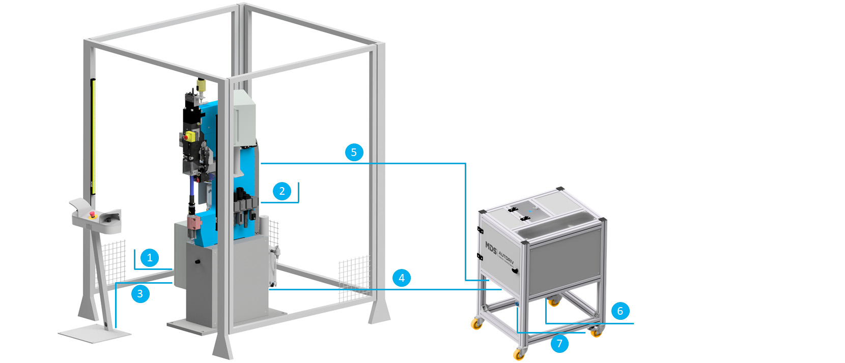
Supply connections
1. Power supply - connection at the control cabinet
2. Compressed air supply - connection on the maintenance unit
3. Signal connection - setting unit and two-hand operation
4. Signal connection - feeding system and setting unit
5. Shot-hose from the feeding system to the setting unit
6. Power supply of the feeding system
7. Compressed air supply of the feeding system
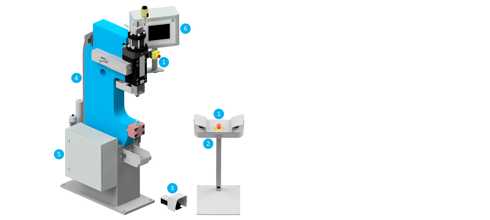
Emergency stop (1)
In dangerous situations, the emergency stop button is actuated. This immediately stops the setting unit and all machine movements.
Two-hand operation (2)
The setting process is started using the two-hand operation. To do this, both keys must be pressed and held down.
Foot operation (alternative) (3)
The setting process starts by pressing the foot switch. After completion of the setting process, the foot switch is released.
Pneumatic maintenance unit (4)
The pneumatic maintenance unit (hidden in the picture) checks, maintains and regulates the incoming compressed air. The pressure regulator can be used to adjust the incoming pressure and shut it off if necessary.
See A240-CP robotic work station for central components of the setting unit.
Control cabinet (5)
The control cabinet contains the electrical and pneumatic control elements. The assembly system is switched on and off via a main switch on the control cabinet.
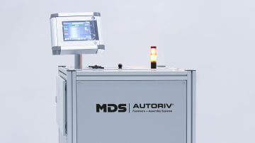
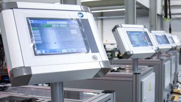
Controller module (6)
The manual work station is operated via the controller module. The control panel can be mounted on the side of the C-frame, on the assembly cell or on the feeding system. In addition, a process evaluation is possible via the software of the control module. A force-displacement curve of the entire setting process is recorded and evaluated.
Operation
Automatic mode
The fasteners are pressed in during automatic mode. The movements are not triggered until the corresponding release signals have been transmitted to the assembly system.
Manual mode
In manual mode, adjustments are made on the setting unit. In this operating mode, movements can be activated individually.
Process safety
The manual work station is positioned in such a way that the operator can easily and safely reach all operating elements so that no dangerous situations can arise. The two-hand operation is positioned approx. 500mm away from the danger zone.
Technical data
Operating air pressure
Electrical power supply
Setting stroke max.
Setting force max. (version "standard" / "strong")
Jaw height / setting stroke
Groove depth
Effective line length from setting unit to feeding system
Noise emissions
Interface connection
Dimensions (L x W x H)
Values apply to a working height of 1000mm
Version 80 kN or 150 kN
Weight
Version 80 kN
Version 150 kN
See A240-CP robotic work station for more details.
6 bar
24 V / 4 A
14 mm
80 kN / 150 kN
150mm; 200mm; 250mm
250mm; 350mm; 450mm; 600mm; 750mm
5 m (standard)
approx. 78 dB(A)
Profinet (standard), Profibus, EtherNet/IP, DeviceNet
from 1100 x 400 x 1800 mm to 1500 x 650 x 1900 mm
from 530 kg to 1220 kg
from 780 kg to 1950 kg


Request for quotation
Would you like us to call you back? Leave your telephone number or e-mail and we will get back to you as soon as possible!