More than a standard solution
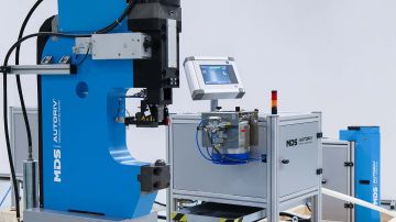
Development and automation of special design fasteners
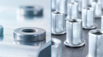
We offer more than just a standard solution for you. In addition to our standard fasteners, we also offer customized fasteners that we design and automate especially for you. We are happy to support you with our large development capacity and many years of experience as a toolmaker in the realization of your project.
Contact us
Our customer service will help you with any questions!
Customized developments are our strength
Some projects cannot be realized with standard solutions. Thus, custom design fasteners with suitable automation are required. However, most system suppliers only sell standard products. Fastener manufacturers also often only have standard fasteners in their product range.
Finding a vendor who is also capable of developing customized fasteners is not easy. You will also not find another system supplier who does both developing special design fasteners and corresponding automation.
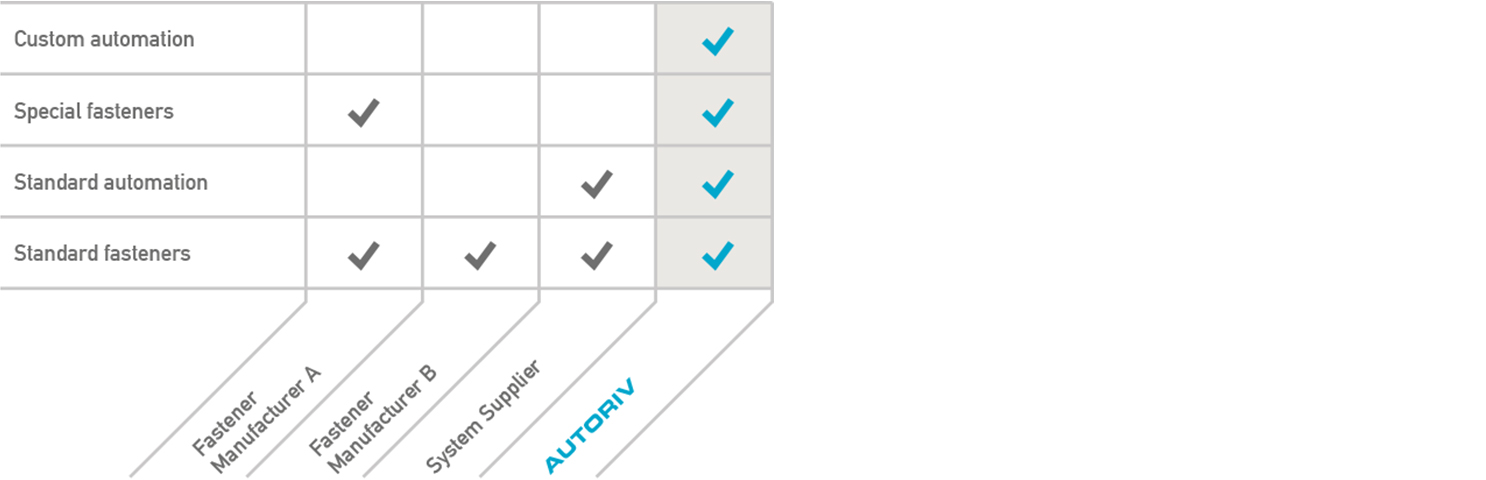
Thanks to our many years of experience as a toolmaker and our large development capacity, custom developments are our strength and a unique selling point on the market. Our special solutions come from our modular system, which has been built up over decades and proven in series production.
Your benefits
- Many years of experience as a toolmaker and know-how in both fasteners and their automation distinguishes us from other system suppliers
- Guaranteed process-reliable automation
- Standard and special solutions based on our tested and proven modular systems
- Short development and delivery times with low costs and high availability
Adaptations
for difficult installation situations
It is often necessary to place fasteners in angular positions to meet difficult installation situations.
On request, we can also offer special solutions for the installation of fasteners in hard-to-reach places, in tight installation spaces or at specific angles, such as:
- Clinch nuts at an angle of 60 degrees
- Combination of rivet nut and spacer at an angle of 90 degrees to the working direction
Further possible adaptations:
- Adaptation to a special fastener
- Adaptation to a special tool environment
- Individual application direction and fastener delivery
- Adaptation to the workpiece to be processed and the required component depths
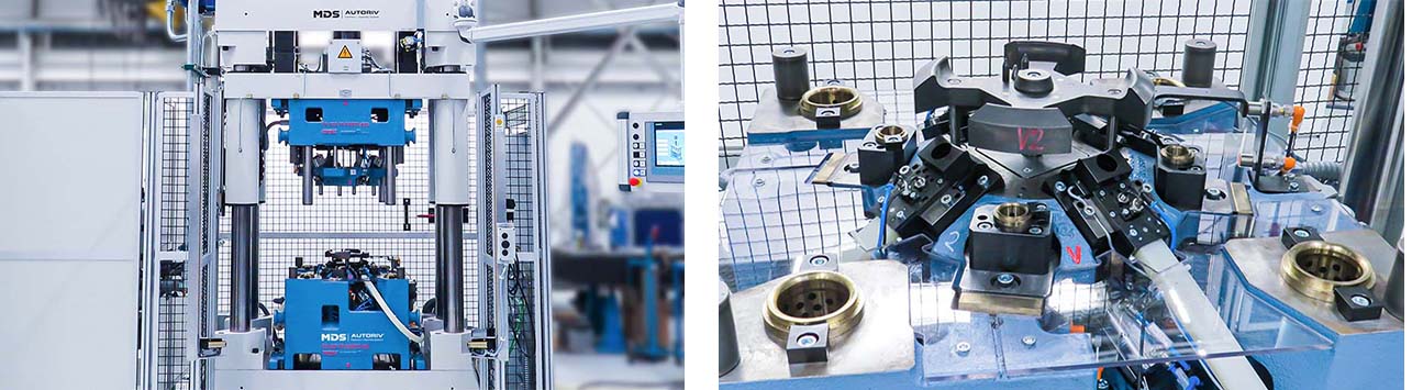
Automation of special design fasteners
If your specific requirements cannot be met with our standard application, we will be happy to provide you with a suitable custom solution. We are able to realize all conceivable requirements if standards are not sufficient for this. Our proven modular system is the foundation for this.
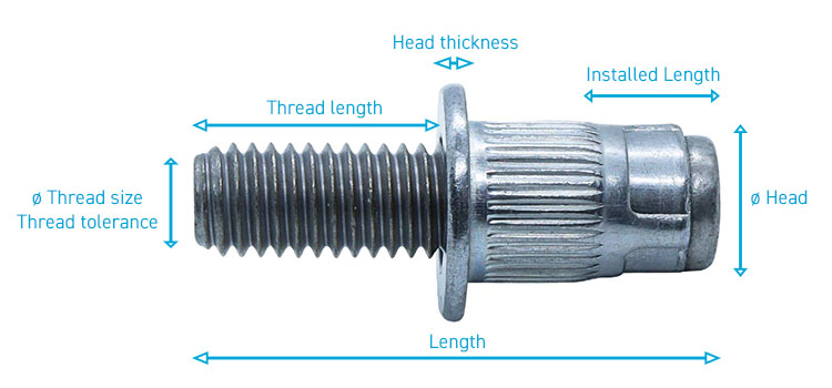
We are happy to make adjustments to our standard fasteners for you. A variety of parameters, related to the field of application, geometry, characteristics and surface of the fastener, are optimized according to your requirements.
Application example
Rivet nut and spacer bushing in a transfer tool
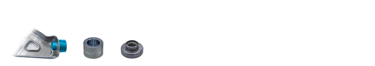
Our customer's task was to develop a combination of a rivet nut and spacer bushing. These two fasteners should be automatically assembled in just one single stage in the transfer tool. This setting process takes place in a a single die station, which is at a 90-degree angle to the stamping direction. This is done in a very small working area.
We have developed the fasteners required for this, rivet nut and spacer bushing. We have run through a series of necessary application tests to validate the process.
The fasteners were developed with the consideration of being able to set them process-safely in the transfer tool. Thus, the development of fasteners took place simultaneously with the development of the automation technology.
With our profound know-how in the critical areas, a project of this complexity could be realized effectively and successfully.
Application example
Special rivet and bushing in a progressive die
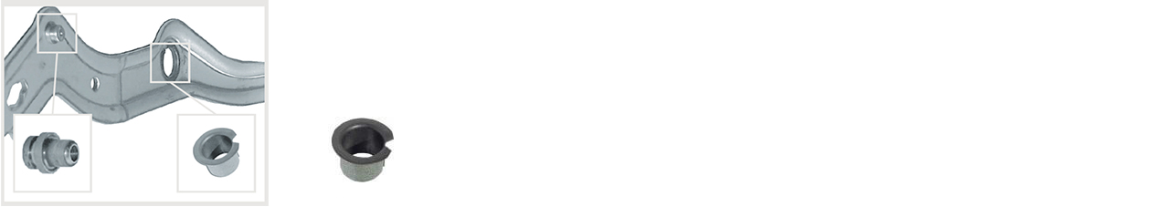
The task was to assemble our special design fasteners, a special rivet and a glide bearing bushing with a wall thickness of 0.5 mm, automatically by flanging with calibration of the inside diameter in a progressive die.
Initially, the assembly of this component should have been done completely outside the press in a subsequent operation as orbital riveting. Due to a detail modification in the riveting area, we were able to bypass the orbital riveting process and assemble both fasteners under the press. This eliminated various subsequent work steps, which resulted in significant cost savings for our customer.
For this application, we were also the only supplier who could realize a project of this complexity effectively and successfully.
Application example
Blind rivet nut with special design for series production
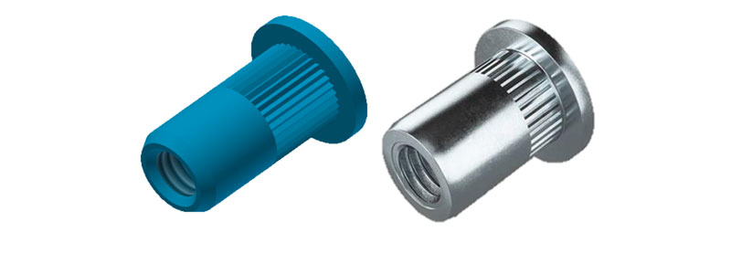
A recent application of blind-rivet nuts in an MDS assembly system led to problems regarding the performance values and the hole detection. The selected standard element by a competitor was used beyond the border area and could thus no longer fulfill the requirements.
Through optimizations in the clamping area and the threading tip, MDS has been able to guarantee the performance of the blind-rivet nut as well as its successful setting process. These adjustments in combination with an optimized supply chain for the lateral entry into the series, the production can now be continued without any problems.