Setting head for clinch studs at high cycle times
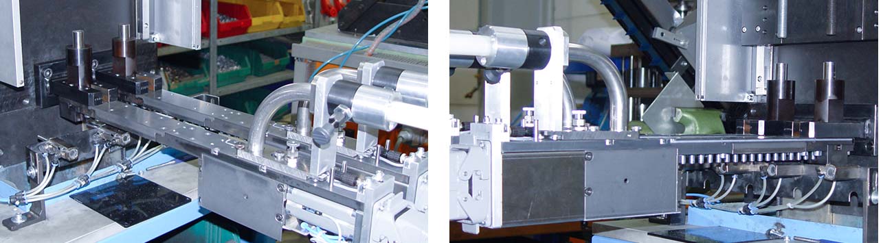
Installation under the press in punching and forming tools
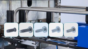
The setting head KOS-HS (Compact System for Studs - High Speed) is an assembly system for progressive dies and transfer dies. The punching head is installed in the press to insert clinch studs into sheet metal components during the press process.
The setting head is particularly suitable for higher cycle rates from 35-40 strokes/min.
Depending on the type of tool and the press, there are different applications for the punching head
- Progressive dies with or without automatic mode signal from the press
- Transfer dies, with or without automatic mode signal from the press and with querying sheet metal in the die or in the gripper
Contact us
Our customer service will help you with any questions!


Installation and processing
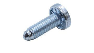
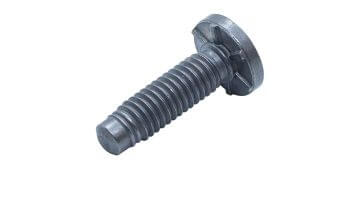
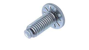
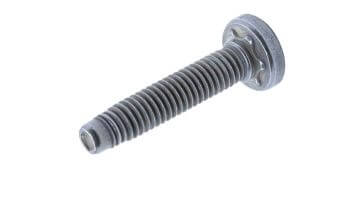
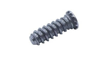
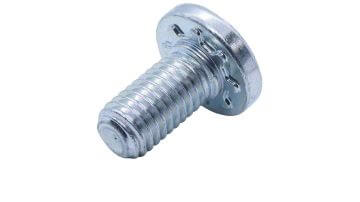
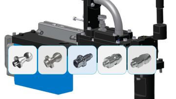
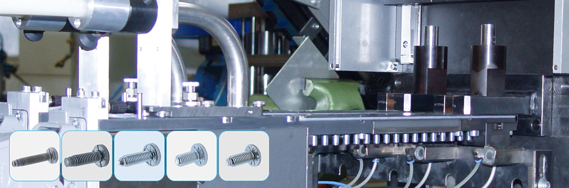
The setting head processes screw-type fasteners with a head that are pressed in with the shank first.
The punching head can be installed in the tool so that clinch studs can be set in the sheet metal from either top or bottom.
Storage of additional fasteners in the setting head allows for short cycle times or high output. This ensures consistent production.
Function
Setting process
The setting head is connected to the associated feeding system for press applications and is supplied with clinch studs via a shot hose. The clinch studs are attached to the heads and stored in a magazine in the setting head. After each press stroke, a new clinch stud moves to the setting position to be pressed into the part on the next stroke. When a clinch stud is in the setting position, a release signal is sent to the press. Without a release signal, the press stops.
Main process
The main process co-ordinates the part request to the feeding system. It ensures that the clinch studs are moved to the setting position on time and monitors the press strokes by interrogating the press cams.
Pressing
The clinch stud is pressed into a sheet metal part from the setting position by the press-in mandrel. If no workpiece is present during a press stroke, no clinch stud is moved to the setting position. The plunger remains at top dead center due to blank sensing. An idle stroke is performed.
Air supply
A pneumatic connection on the feed system transfers compressed air to the setting head. This connection supplies the permanent air, the pneumatic cylinder for the slider and, optionally, the press-in mandrel.
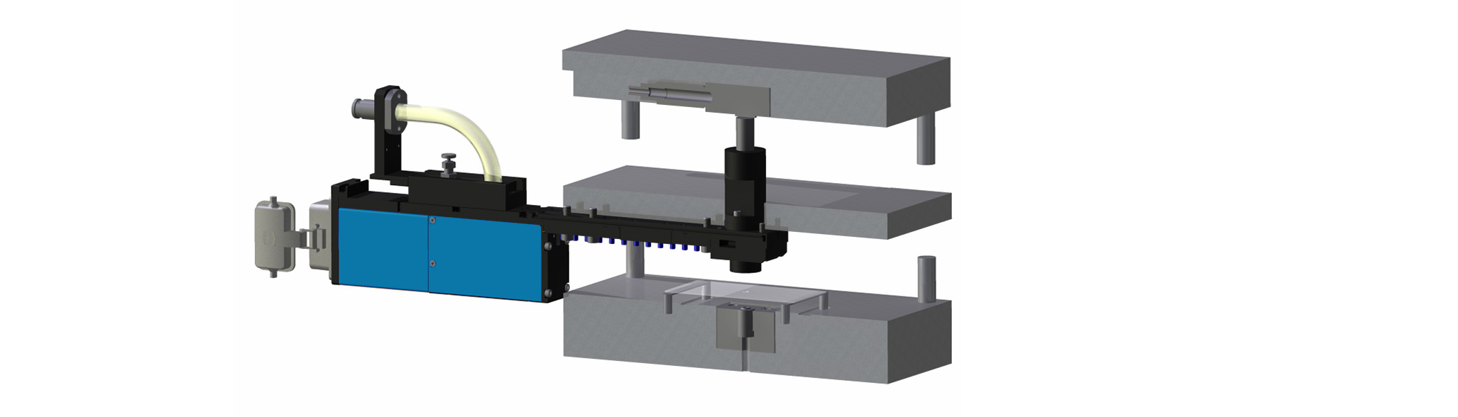
Components
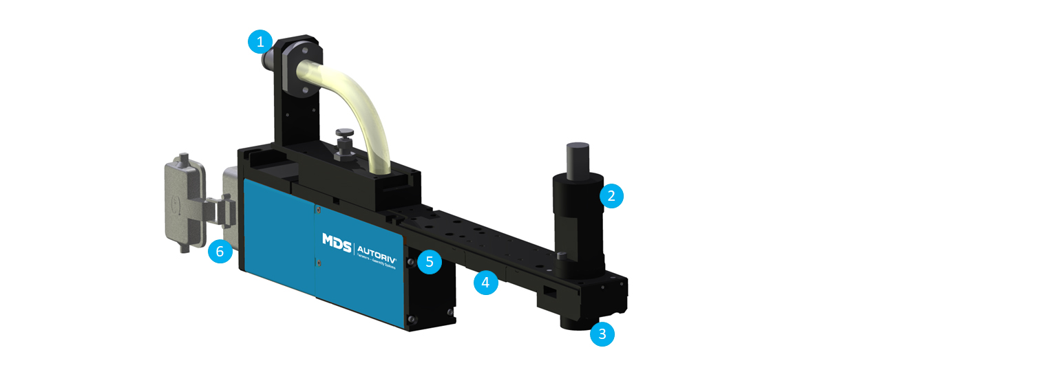
Connector plug (1)
The connector plug is used to connect the shot tube to the setting head. The coupling is held in place by a locking pin on the connector plug of the punching head. The clinch stud is transported via the screw feed (bent tube) into the accumulation path.
Plunger (2)
The plunger houses the press-in mandrel, which presses the clinch studs into the sheet metal component. The mandrel is actuated by closing the press and transmits the compression force to the fastener. When the press is opened, the mandrel is pneumatically returned to the home position.
Impact piece (3)
The impact piece guides the clinch stud during the press-in process.
Accumulation path (4)
The setting head includes an accumulation path. It is used to store additional clinch studs in the punching head to compensate for feed fluctuatons. A pneumatic cylinder pushes the fasteners forward to the setting position. The accumulation path ensures consistent production.
Feed cylinder (5)
The screw transport pushes the fastener forward to fill the accumulation path.
Multifunctional hose connector (6)
All signals are transmitted from the setting head to the feeding system via the multifunctional hose. The multifunctional hose also provides pneumatic supply to the punching head.
Highlights
High production reliability and quality
All important functions in the setting head are sensor-monitored with communication to the feeding system to stop the press in case of a malfunction well before top dead center (TDC) and thus avoid die damage.
Fast stroke rates
If a fastener is in the setting position and still being processed, the next fastener can already be reloaded. The next fastener can therefore be shot into the setting head in parallel with the processing of one fastener. This means that higher processing speeds can be achieved even with long shot hose lengths.
Safety during coil changes and with empty parts in production (transfer dies)
The screw transport only moves to the set position when a clinch stud is to be installed. Transfer die: If there is no workpiece, the feed cylinder does not move to the set position. It moves when a workpiece is present. The empty part sensor is either in the transfer grippers or in the tool itself. Coil change: When a coil change is required, the feed cylinder remains in the home position and the coil can be retracted as if there were no setting head installed in the tool.
Quick commissioning
The setting head has quick-release couplings for the shot hose and the multifunction hose for communication with the feeding system. There is no need to connect individual cables. This saves time and eliminates connection errors.
Technical data
Installation width:
Pneumatic supply:
Control voltage:
Press-in force / path:
Cycle time:
Interfering edge / Possible component depth:
Working direction:
*Depending on the fastener and length of the shot hose.
50 / 60 / 70 / 80 mm
6 bar from feeding system
24 V / DC from feeding system
tool-dependent
up to 80 cycles/min*
according to customer requirements
vertical in both directions
Request for quotation
Would you like us to call you back? Leave your telephone number or e-mail and we will get back to you as soon as possible!