Multi-setting system
for processing fasteners

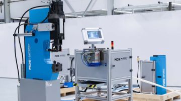
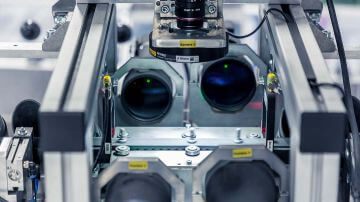
The A250-BI (Blind Inserts) assembly system is a stationary multi-setting system for processing blind rivet fasteners.
In this application example, the multi-setting system includes two mobile setting units for blind rivet fasteners, so the basic structure of the assembly system is similar to "A230-BI mobile robotic tool". The processed component is inserted into the assembly cell by the operator. The setting units are then moved to the component. The blind rivet fasteners are fed in via a feeding system.
Fasteners - blind rivet nuts and blind rivet screws
Body shape - round, hexagonal / fullhex, partial hexagonal / halfhex
Thread size - M5, M6, M8, M10
Outer diameter - min. 10mm - max. 20mm
Height - Lmin. 13mm - Lmax. 30mm (without thread for screws)
Working direction - from top to bottom
Advantages of the system
- Fully automatic, process-reliable processing of fasteners
- Short cycle times
- Efficient tool movements with minimum wear
- Cost savings due to automatic loading, feeding and setting processes
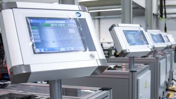
- Feeding system and controller module outside the danger zone
- Process monitoring with force-displacement evaluation
Designs
Setting units for various fasteners
Due to the modular design of the setting system, different combinations of individual setting units are possible. The component can be inserted by the operator or by the robot. The multi-setting system can be integrated into a higher-level system.
Adaptations are made for your special requirements such as:
- Adaptation to the processed component and the required component depths
- Adaptation to the processed fastener - clinching fasteners, blind rivet fasteners, spacers / standoffs, screw fasteners, clips
- Supply with fasteners


Function
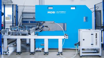
Assembly cell with two A230-BI units - installation of blind rivet nuts and studs
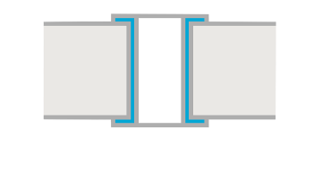
The component - a crossbeam - is inserted into the component holder. The correct position of the inserted component is monitored by sensors. The X-Y portal with the setting units is in the home position, centered behind the component.
The operator starts the sequence. After the start release, the machine safety gate closes. The grippers of the component fixture close, these are self-locking and remain locked even if the pneumatics are interrupted.
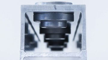
The setting process starts. The X-Y portal is used to move to the positions of the fasteners to be set. The blind rivet fasteners are installed into the component with the corresponding setting unit. The right setting unit is for blind rivet nuts, the left one for blind rivet screws.
Once all blind rivet fasteners have been installed on the first side of the component, the X-Y portal moves to the home position. The locking of the component holder is released and a swivel drive rotates the component holder by 90 degrees. The locking mechanism locks the component fixture again.
Now all blind rivet fasteners of the second surface are set. The component holder is then swiveled again and the blind rivet fasteners of the third surface are set.
When all blind rivet fasteners have been installed correctly, the component holder swivels back to its original starting position. The X-Y portal moves to the home position, the grippers and the safety gate open. The operator removes the component.


Request for quotation
Would you like us to call you back? Leave your telephone number or e-mail and we will get back to you as soon as possible!