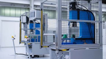
Robotic work station
for processing fasteners
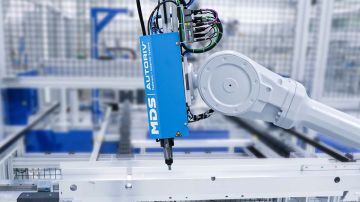
The A240-CP (Clinch Parts) assembly system is a stationary robotic work station for processing clinching fasteners.
The processed component is held by the robot and positioned at the setting unit. The force is applied via a hydropneumatic pressure intensifier and a hydraulic cylinder. The basic functions of the setting unit are automatic loading, feeding of the fastener into the component and the process-monitored setting operation.
Fasteners - clinch nut, rivet nut, self-piercing nut, clinch stud, self-piercing stud / rivet stud
Thread size - M5, M6, M8, M10, M12
Outer diameter - min. 10mm - max. 25mm (clinch nut / self-piercing nut / clinch stud); min. 13mm - max. 28mm (rivet nut)
Overall height - min. 4mm - max. 15mm (clinch nut / self-piercing nut); min. 9mm - max. 16mm (rivet nut)
Studs
Head height - min. 1.5mm - max. 15mm (clinch stud); min. 8mm - max. 15mm (self-piercing stud / rivet stud)
Shank length - max. 30mm (clinch stud); max. 40mm (self-piercing stud / rivet stud)
Overall length - max. 45mm (clinch stud); max. 55mm (self-piercing stud / rivet stud)
Working direction - From top to bottom
Advantages of the system
- Fully automatic, process-reliable processing of clinching fasteners
- Very fast setting movement - double speed compared to other drive systems
- Parallel drive (patented) for efficient tool movements and low wear
- Active tolerance compensation (patented)
- Cost savings due to automatic feeding, loading and setting process
- Feeding system and controller module outside the robot cell
- Process monitoring with force-displacement evaluation
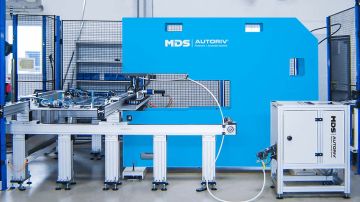
Designs
Robotic work stations for various fasteners
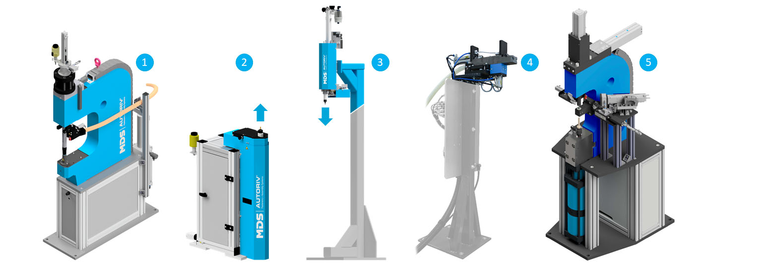
The stationary robotic work stations are available in different versions. Thus, other types of fasteners can be processed:
A240-BI assembly systems (Blind Inserts) for blind rivet nuts, blind rivet studs
The setting process is similar to "A230-BI mobile robotic tool", with the difference that the processed sheet metal component is placed on the blind rivet fastener by the robot, the setting unit is not moved to the component.
Variant with working direction from bottom to top (2).
The electrical and pneumatic components, as well as the pressure intensifier, are housed in a base frame to which the setting unit is attached. Otherwise, the design is similar to A230-BI.
Variant with working direction from top to bottom (3)
This is a variant for setting from above on a gallows according to customer-specific dimensions. The design is similar to A230-BI.
A240-CU assembly system (Clips, U-nuts) for snap-in nuts (4)
This robotic work station is used to push snap-in nuts onto components from the side. The snap-in nut is fed in via a shot-hose and moved into the push-on position. The robot moves the component into position. The push-on cylinder pushes the snap nut sideways onto the component. An optional cylinder provides an additional guide to place the fastener precisely on the component. The push-on cylinder moves back and a new snap-in nut is loaded.
Mounting system A240-NMS for combination of a nut and spacer (5)
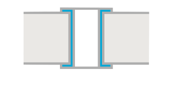
The nut-spacer-combination is a high-strength structural connection for joining positions accessible from one side, e.g. in closed profiles.
This work station is used to set clinch nuts / rivet nuts in combination with additional spacers / washers in a single step. The spacer is inserted into the die button by a transfer mechanism with gripper. A robot places the component on the inserted spacer. The plunger feeds the nut and performs a setting stroke that connects the clinch nut and spacer to the component.
Function
Step 1 - Automatic loading
In the loading position of the setting unit (plunger), there is a sensor that determines whether a fastener is in the holder. In the home position, the setting unit also checks whether a loading process needs to be triggered.
If a clinching fastener is already in the loading position, the setting unit signals "Ready to set" and waits for the request to start the setting process. Otherwise, a fastener is conveyed to the loading position via the separator of the setting unit.
Step 2- Feeding the clinching fastener into the component
After the robot has placed the component on the die, the high-level controller gives a release for pressing. After the setting process has started, the plunger and the intermediate piece are moved into the working position.
As soon as the displacement measurement system has been pressed and has come to rest, it is checked whether the measured value is within a parameterized tolerance range. Then the pressing process is started.
If the material thickness is unsuitable, the setting unit issues an error message, does not press and moves back to the home position.
Step 3 - Process-monitored setting operation
After a successful preliminary check of the displacement measurement system, the setting process is initiated and a stroke is executed.
If the displacement measurement system detects no more deformation, the pressing operation is finished and the press returns to the home position. The result of the force-displacement evaluation is issued. After completion of the setting process, the setting unit is moved back to the home position. A completion message is sent to the robot.


Components
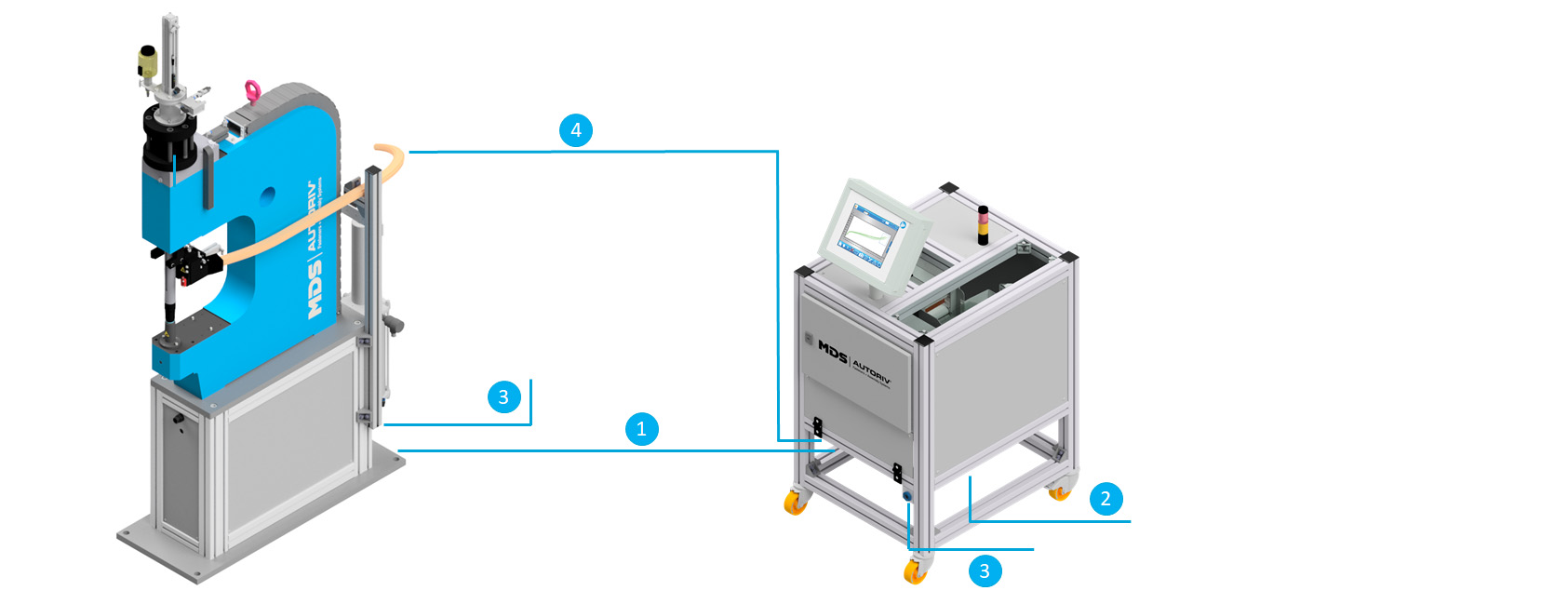
The robotic work station is designed for installation in a robot cell system. The clinching fasteners are fed via a feeding system. The clinching fasteners are transported to the setting unit via a shot-hose. The effective length of the shot-hose from the feeding system to the setting unit is 5 meters. Special lengths are possible.
The pneumatic valves of the setting unit are supplied with air via a compressed air connection. The control connection is used for the signal connection of the setting unit with the feeding system and for the power supply.
Supply connections
1. Control and power supply from the feeding system to the setting unit
2. Control and power supply from the robot cell to the feeding system
3. Pneumatic supply / compressed air
4. Shot-hose from the feeding system to the setting unit
Due to the modular design of the assembly system, depths of grooves from 250mm to 750mm and different jaw heights from 150mm to 250mm are possible - adapted to individual components at optimum cycle times. A smaller jaw height (setting stroke) positively influences the cycle time. The depth of groove ensures the machining of large, widely projecting components.
The base below the C-frame contains the electrical and pneumatic control elements and protects them from external influences.
Separation
The clinching fastener is conveyed to the loading position via the separator of the setting unit. Depending on the type of fastener, different separation variants are used:
Separator for clinch nuts / self-piercing nuts - A pusher separates a clinch nut at the end of the accumulation path and pushes it into the nut receptor.
X-Z separator for rivet nuts - At the end of the accumulation path, the nut is lifted by two cylinders into the nut receptor of the plunger.
Separator for clinch studs / rivet studs - A swivel construction is swiveled under the plunger and the stud is blown into the plunger receptor by a blow-out nozzle.
It is possible to convey additional studs to congestion with an optional pre-separation, thus significantly reducing the cycle time. This accumulating path is monitored by two sensors. Due to the availability of this additional magazine in the setting unit, the length of the shot hose and the associated shot time have no influence on the cycle time.
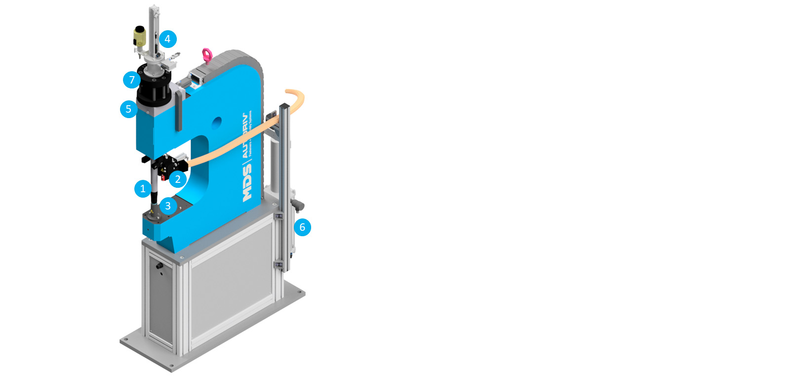
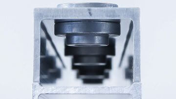
Plunger (1)
The plunger is used to transmit force between the setting cylinder and the component. The clinching fastener is fed into the component and pressed via the holder on the plunger.
Die button (3)
The processed component is positioned by the robot on the die button at the C-frame. The die unit is either fixed or floating.
Active tolerance compensation - The floating die for nuts enables active tolerance compensation (patented). For bolts, the compensation is performed by the floating robot gripper.
Displacement measurement system (4)
The displacement measurement system measures the distance covered by the plunger during the clinching process. The quality of the pressing is determined by the press-in pressure and the travel of the plunger. The displacement measurement system only triggers the setting stroke if the infeed occurs within the defined displacement tolerance. To prevent the fastener from hitting the component hard, a throttle is installed to slow down the plunger cylinder shortly before impact. The time of throttling is determined by a sensor.
Intermediate piece (5)
The setting unit uses a patented method of transmitting force to the plunger - after the plunger has fed the fastener into the component, a mechanical intermediate piece is moved between the hydraulic cylinder and plunger. Only when the intermediate piece is retracted can force be transmitted to the fastener by the setting cylinder. The intermediate piece can only be retracted when the plunger is completely extended. This leaves only a narrow gap between the fastener and the component before pressing force can be applied. This means that an operator cannot bring any limbs into the press - making the system particularly safe.
Pressure booster (6)
The pressure booster generates the required hydraulic pressure. For this purpose pneumatic pressure is converted into hydraulic pressure. The higher the pneumatic pressure, the higher the hydraulic pressure. The pressure booster is divided into a pneumatic and a hydraulic part.
Hydraulic cylinder (7)
The hydraulic cylinder / setting cylinder generates the force required to press the fastener to the component. The cylinder is moved to its working position with hydraulic pressure and moved back to its home position with pneumatic pressure.
Technical data
Operating air pressure
Electrical power supply
Setting stroke max.
Setting force max. (version "standard" / "strong")
Jaw height / setting stroke
Groove depth
Effective line length from setting unit to feeding system
Noise emissions
Interface connection
Cycle time
Reference - Clinch stud M6, version - 80 kN, setting force - 40 kN
Rod cylinder fastener - travel time home position to working position
Rod cylinder fastener - travel time working position to home position
Stroke reduction cylinder
Cycle time - time from home position to home position
Setting time - "Start" signal from the higher-level controller to "Home position" signal from the setting unit
Dimensions (L x W x H)
Values apply to a working height of 1000mm
Version 80 kN
Version 150 kN
Weight
Version 80 kN
Version 150 kN
6 bar
24 V / 4 A
14 mm
80 kN / 150 kN
150mm; 200mm; 250mm
250mm; 350mm; 450mm; 600mm; 750mm
5 m (standard)
approx. 78 dB(A)
Profinet (standard), Profibus, EtherNet/IP, DeviceNet
0,8 s
0,4 s
0,2 s
3,9 s
2,13 s
from 940 x 423 x 2025 mm to 1638 x 423 x 2225 mm
from 1000 x 423 x 2196 mm to 1800 x 423 x 2396 mm
from 500 kg to 1200 kg
from 750 kg to 1850 kg


Request for quotation
Would you like us to call you back? Leave your telephone number or e-mail and we will get back to you as soon as possible!